![]()
![]()
![]()
![]()
![]()
![]()
![]()
![]()
![]()
![]()
|
|
||||
| Lost Foam epoxy glass forming technique | ||||
|
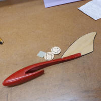
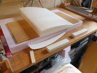
Creating a form using a lost foam technique is a fantastic technique if you are making a one-off item. Whether its a fuselage for a new prototype project, or even a fuselage to match a set of wings you may have acquired, cowlings, fairings, or just about anything. The best thing is its not expensive, and is a rewarding way of making something. Essentially, you create a polystyrene shape, cover it in glass cloth and epoxy, then once cured, you dig and melt the foam from within the shape. Its a little messy, but it all cleans up well. The following is just one such project that I recently undertook for a friend, but check out the other projects I have produced at the foot of the page...... Spitfire Oil Cooler Duct Fairings It was at the end of
my local model club scale event with people dismantling their scale
creations or partaking in a little fun flying, that a friend approached
me with a request for help. I had watched his Spitfire take flight, but
what I hadn’t realised it didn’t have the Oil Cooler Duct Fairings
fitted underneath the wing. Well, it might have had during flight, but
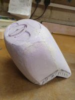
when he showed me the ori Once at home I scrutinised the mouldings and decided that white foam could be used for the job and I just happened to have a couple of small blocks of polystyrene in the corner of the workshop. Whilst I could have carved and sand the top surface I decided that
given that the curve was akin to the top surface of a win which I could
cut with the hot wire wing bow. It just so happens that the curve was a
close match to the aerofoil of the Super-Fli aerobatic model , so I just
cut the top surface of the foam. Well, it just meant
that it was quicker and less messy than carving and sanding and as I cut
one long piece of foam, once trimmed and cut to size I could guarantee
that both would have the same accurate curve to the top surface.
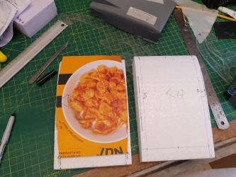
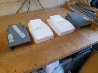
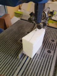
The Plan format revealed that each fairing was handed with the outer side being more curved than the inner side by 4mm. I made a cardboard template, marked up the foam. I cut the basic shape on the bandsaw and used my disc sander to whittle it down further to the right shape…….. That was easy! I did notice later, that there was a L and an R subtly marked on the original plastic mouldings, but I’d worked it out correctly anyway. Next was the trailing edge protrusion which was again, cut on the bandsaw and stuck to the main structure with wood glue. I also noticed that the leading edges to the intake were curved so I shaped some closed cell foam (Blue foam) due to the fact it is easier to shape and sand than polystyrene to make smaller items. These were essentially the same shape as a leading edge to a small wing which I stuck on with wood glue. I had some balsa leading edge strips, but I didn’t want to waste balsa, but in hindsight, I could have left these in place to strengthen the intake…. But I did it a different way….
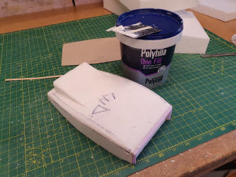
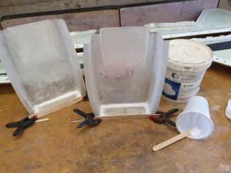
Once everything was stuck together, the corners of the structures were rounded off and filler (Polyfilla – One Fill) applied to blend the 2 profiles and seamlessly mask the glue line to the rear protrusion. Once dry and sanded, the foam structures were complete, they just needed the epoxy and glass cloth applying to finish. A good and strong
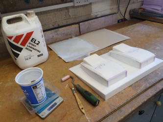
lay up for epoxy and cloth, which I use on my smaller fibreglass
fuselages is a mix of 3 layers of glass cloth: 1x 80g and 2x 160g cloth.
(Multiple layers of cloth is much stronger than a single layer
corresponding to the same thickness (320g) and is so much easier to work
with and get it to conform to more intricate shapes. The sizes of 160g
cloth required for this job were matched from my off cuts box with
additional 2 pieces of 80g cloth having to be cut off the roll as I only
had a few small bits in my offcut stash and didn’t want to join multiple
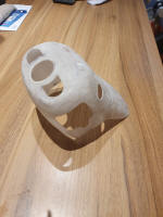
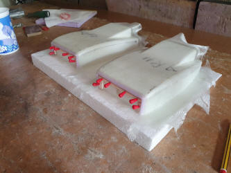
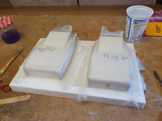
pieces. Starting the moulding: The first layer (160g) cut on the bias (45 Deg) was laid over the foam in one piece and given that it was “Twill” weave means that it draped over and conformed to the structure well with little persuasion, only having to cut it at the front to conform to the curved leading edges of the duct intake. I also overlapped the cloth onto the base to form a flange just in case Andrew wanted to mount the ducts in this way (the originals didn’t have a flange around the whole structure) but these could be easily cut off later. Whilst the first layer was still wet and uncured, I followed with a second layer of 160g cloth and finally the 80g cloth all laid on the bias (at 45 Deg). The cloth didn’t really want to stick consistently to the inner part of the intake, it seemed to ease away from the shape as the cloth settled, so I pinned a couple of strips of 1/8” balsa to maintain the shape whilst the whole thing cured.
I left these overnight in the garage / workshop. In the morning it was still a little tacky so I put them into the warm airing cupboard to cure properly. The next day the new ducts were cured enough to work on them. I dusted talc over the outer surfaces so they didn’t clog the sandpaper too much and I set to sanding down the rough edges and basically reducing the feel of the textile weft and warp of the cloth. This was followed by wet, 600 grade Wet-n-Dry to get a smoother surface.
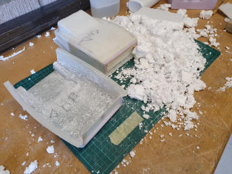
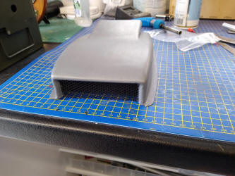
That done and happy with the finish, all that was left to do was dig out the foam. Yes, it’s messy and with the white foam, it gets statically charged and sticks to everything. It wouldn’t be the first or last time I have had to vacuum myself down afterwards. The foam was removed by carving, digging and sanding, finished off by a light use of cellulose thinners to remove the bits stubbornly stuck to the epoxy and in the areas where trying to remove the foam by cutting and sanding was difficult. The thinners seem to soften the epoxy/glass structure but this is only temporary, as once it’s washed with soapy water and dried it soon hardens up again.
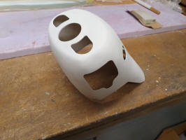
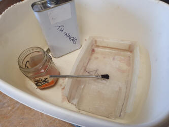
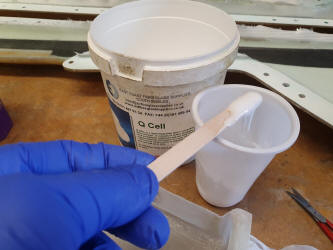
The leading edges of the duct intake seemed flimsy on the original plastic moulding and I assumed would be on the new structures once trimmed, so I decided to fill these with epoxy and micro balloons. (This is where in hindsight, I could have used balsa Leading edge stock or carved balsa to form the intake leading edge). I know it say “Q cells” on the filler tub in the photo, but I assure you, these are essentially the same as Micro balloons – little glass beads that mix well with resin to form a filler paste. Mixed with resin to a consistency of toothpaste it was applied with a lolly stick to fill the void and allow to self-level and left to cure. Once cured this can be cut and sanded back easily, not that I needed to sand these back. (The epoxy / micro balloon gloop makes a great filler in foam wings – I use it to form false trailing edges in vac bagged moulded wings. It can be carved, trimmed with a razor plane and sanded with relative ease)
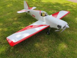
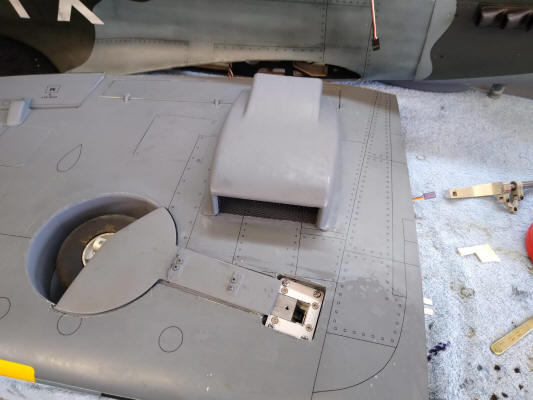
The last thing to do was to trim the intake openings with my Dremel cutting tool and all was complete. Quite pleased with the outcome I contacted my friend, who just so happened had just arrived down the local club field. I eagerly put a model in the car to have a fix once down the field and took the trip to meet up with my firend and hand over the new spitfire duct fairings. I asked him to take a photo of the new ducts once they had been painted and fitted to the Spitfire. All that was left was to have a few flights before going home for tea and medals, with the satisfaction of another job well done….. My friend has since painted the fairings and inserted some black mesh into the intake which I think looks pretty cool.
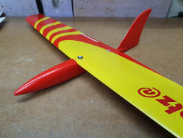
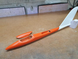
I hope this has inspired a few of you to consider using the lost foam technique to make one-off moulding. You get a great sense of achievement at creating something that is far cheaper and stronger than the spares you may have to buy, if indeed you can get the spares. Tools for the job are minimal, a hand saw or kitchen knife / Stanley knife to cut the foam. A coarse file (Didn’t want to be rude) and various grade of sand paper, if you have some Permagrit tools, then so much the better, and wet n dry for the final job. You don’t need much resin, the above job took about 60g of resin overall. A brush or roller to apply the resin. (Most people have these in their workshops don’t they???) I find methylated spirit great for cleaning up the epoxy resin and brushes. And you will need some PPE – Especially the gloves. I have previously made cowlings, undercarriage fairings and also used the same “Lost Foam” technique to make prototype fuselage for my own design gliders. My first one was not the best, but it was good enough for the job. As time and experience has progressed, each successive fuselage or other moulding has been better than the last. Other than the woven glass cloth,
My sources of consumables as follows: Buck Composites (Great for small quantities) https://www.bucks-composites.com/ East Coast Fibreglass Supplies https://www.ecfibreglasssupplies.co.uk/ Easy Composites https://www.easycomposites.co.uk/
Check out the photos of the other Lost foam projects I have undertaken:
|
||||
|
Super-Fli Cowling |
 |
|||
|
Prototype Fuselages: |
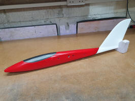 Volitan |
 X-1 Prototype |
Wotzat Prototype |
 XLS / Hotshot Prototype |
 ginals,
they had clearly been taken off the model. They were made of thin ABS
plastic and were not really robust enough for the job and clearly one of
them had been repaired previously. I was asked if I could create some
magic and produce some more robust fairings. It shouldn’t be a problem
and indeed, it worked out quite an easy task. I have highlighted the use
of the “Lost Foam” technique to make one-off fibreglass moulding
previously and these fairings would easily lend themselves to this
technique, so I agree to make them.
ginals,
they had clearly been taken off the model. They were made of thin ABS
plastic and were not really robust enough for the job and clearly one of
them had been repaired previously. I was asked if I could create some
magic and produce some more robust fairings. It shouldn’t be a problem
and indeed, it worked out quite an easy task. I have highlighted the use
of the “Lost Foam” technique to make one-off fibreglass moulding
previously and these fairings would easily lend themselves to this
technique, so I agree to make them.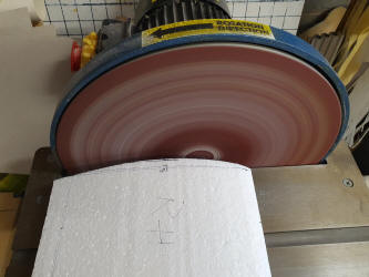
 If
it all goes wrong, you haven’t lost much, just a few materials, and you
can always try again.
If
it all goes wrong, you haven’t lost much, just a few materials, and you
can always try again.